Core: Cross Sections
The functions in this section enable you to access, modify, and delete cross sections, and create planar cross sections.
Listing Cross Sections
Functions Introduced:
The function ProXsecRename() renames a specified cross section.
Use function ProXsecTypeGet() to retrieve the type of cross section. The input argument for this function is a handle to the specified cross section. The output argument p_type is a ProXsecType structure, which contains the following fields:
•  cutter—Specifies the cutting object type. The valid cutting object types are contained in the enumerated type ProXsecCut and are as follows:
  PRO_XSEC_PLANAR
  PRO_XSEC_OFFSET
  PRO_XSEC_PATTERN
•  cut_object—Specifies the object that was cut. The valid object types are contained in the enumerated type ProXsecCutobj and are as follows:
  PRO_XSECTYPE_MODEL—Specifies that the cross section was created on solid geometry.
  PRO_XSECTYPE_QUILTS—Specifies that the cross section was created on one quilt surface.
  PRO_XSECTYPE_MODELQUILTS—Specifies that the cross section was created on solid geometry and all quilt surfaces.
  PRO_XSECTYPE_ONEPART—Specifies that the cross section was created on one component in the assembly.
Extracting Cross-Sectional Geometry
Functions Introduced:
Superseded Functions:
The geometry of a cross section in an assembly is divided into components. Each component corresponds to one of the parts in the assembly that is intersected by the cross section, and describes the geometry of that intersection. A component can have disjoint geometry if the cross section intersects a given part instance in more than one place.
A cross section in a part has a single component.
The components of a cross section are identified by consecutive integer identifiers that always start at 0.
The function ProXsecGeometryCollect() returns an array containing the geometry of all components in the specified cross section. The function ProXsecGeometryCollect() supersedes the function ProXsecGeometryRetrieve().
The function ProXsecGeometryRetrieve() returns an array containing the geometry of all components in the specified cross section and retrieves the following information about a specified cross-sectional component:
•  The memb_num and memb_id_tab for the intersected part, with respect to the assembly that contains the cross section.
•  A handle to the geometry of the intersection.
The geometry handle can be treated as an ordinary face pointer. Extract its contours with function ProSurfaceContourVisit().
Use the function ProXsecGeometryArrayFree() to free the memory allocated to the array of cross section data and use the function ProXsecGeometryFree() to free memory allocated to the cross section data.
The geometry of a cross section is not maintained constantly by Creo Parametric—it is regenerated only when the user requests to see the cross section. Use function ProXsecRegenerate() to regenerate the cross-section of a part or an assembly. Use function ProXsecDisplay() to display a cross section. ProXsecDisplay() does not add the cross section to the associated objects list, and the displayed cross section disappears on the first screen redraw.
The function ProXsecPlaneGet() returns the plane geometry for a specified cross section.
The function ProOffsetXsecGet() returns the following parameters for a specified offset cross section.
•  p_ent_arr—Specifies the cross section entities.
•  plane—Specifies an entity plane.
•  p_one_sided—If this output argument is true, the cross section lies on one side of the entity plane, if it is false, the cross section is both-sided.
•  p_flip—If this output argument is false, Creo Parametric removes material from the left of the cross section entities if the viewing direction is from the positive side of the entity plane. If p_flip is true, Creo Parametric retains the material from the left of the cross section entities and removes the rest of the material.
The function ProXsecGet() retrieves the cross section handle based on the specified solid model and cross section ID.
The function ProXsecAsModelitemGet() converts a cross section handle into an appropriate model item.
The function ProXsecFlipGet() returns a integer value that indicates the direction in which the cross section has been clipped. Depending on the type of cross section, the integer value indicates different direction of clipping as below:
•  Planar cross section—The integer value:
  1 indicates that the cross section has been clipped in the direction of the positive normal to the cross section plane.
  -1 indicates that the cross section has been clipped in the opposite direction of the positive normal.
•  Offset cross section—The integer value:
  1 indicates that material has been removed from the left of the cross section entities if the viewing direction is from the positive side of the entity plane.
  -1 indicates that the material has been retained from the left of the cross section entities and rest of the material has been removed.
The function ProXsecExcludeCompGet() returns the status and an array of paths to the assembly components that have been included and excluded for the specified cross section. The assembly paths are returned as a ProArray of type ProAsmpath. The status of the assembly components is returned by the enumerated type ProXsecExcludeModels and the valid values are:
•  PRO_XSEC_MODEL_EXCLUDE—Specifies that the assembly components has been excluded.
•  PRO_XSEC_MODEL_INCLUDE—Specifies that the assembly components has been included.
Use the function ProAsmpathProarrayFree() to free the memory allocated to the ProArray of type ProAsmpath.
Visiting Cross Sections
Function Introduced:
The function ProSolidXsecVisit() enables you to visit all named cross sections in the specified solid. Use ProSolidXsecVisitAction() to supply the function to be performed when visiting part or assembly cross sections.
Creating and Modifying Cross Sections
Functions Introduced:
The function ProXsecParallelCreate() creates a cross section feature parallel to a given plane.
The function ProXsecPlanarWithoptionsCreate() creates a cross section feature through a datum plane and also makes the cross section visible. The input arguments are:
•  solid_owner—Specifies the model where the cross section will be created.
•  xsec_name—Specifies the name of the cross section.
•  plane_id—Specifies the ID of the cutting plane. The cutting plane must belong to the model.
•  xsec_type—Specifies the type of object that will be cut by the cross section. It is specified by the enumerated type ProXsecCutobj.
•  memb_id_tab—Specifies the path to:
  The assembly component which contains the quilt being cut, when xsec_type is set to PRO_XSECTYPE_QUILTS. Here only the quilt with specified quit_id is cut in the component.
  The assembly component which contains the solid geometry being cut, when xsec_type is set to PRO_XSECTYPE_ONEPART. Here only the solid geometry of the component is cut.
  Specify the input parameter as NULL for all the other object types defined in ProXsecCutobj.
•  Specifies the path to the assembly component being cut. If the xsec_type is PRO_XSECTYPE_QUILTS, then only the quilt with specified quit_id is cut in this component. If the xsec_type is PRO_XSECTYPE_ONEPART, then only solid geometry of this component is cut.
•  quilt_id—Specifies the ID of the quilt when xsec_type is PRO_XSECTYPE_QUILTS. The quilt must belong to the top assembly or any of its sub-assemblies and parts. When the object to be cut is not a quilt specify the value as 1.
•  flip—Specifies the direction in which the cross section will be clipped. The value 1 indicates that the cross section will be clipped in the direction of the positive normal to the cutting plane. -1 indicates that the cross section will be clipped in the opposite direction of the positive normal.
•  model_opt—Specifies if the assembly components must be included or excluded while creating the cross section. The status of the assembly components can be set using the enumerated data type ProXsecExcludeModels.
•  comp_id_tabs—Specifies an array of paths to the assembly components that have been included and excluded for the specified cross section. The assembly paths are set as a ProArray of type ProAsmpath. Use the function ProAsmpathProarrayFree() to free the memory allocated to the ProArray of type ProAsmpath.
Note
•  From Creo Parametric 4.0 F000 onward, when a cross section is created, it is not displayed by default in the model. You must call the function ProXsecMakeVisible() to display the cross section.
•  While porting Creo Parametric TOOLKIT applications, which have used the function ProXsecPlanarWithoptionsCreate() and have been created in releases prior to Creo Parametric 4.0 F000, depending on whether you want the cross section to be displayed, call the function ProXsecMakeVisible() in your applications. ProXsecMakeVisible() displays the cross section in the model.
•  From Creo Parametric 2.0 onward:
  the legacy cross sections, that is, the cross sections created in Pro/ENGINEER, Creo Elements/Pro, and in releases prior to Creo Parametric 2.0 are not supported.
  the functions ProXsecParallelCreate() and ProXsecPlanarWithoptionsCreate() create cross sections as features.
  the functions ProXsecParallelCreate() and ProXsecPlanarWithoptionsCreate() automatically convert the legacy cross sections to new cross section features as defined in Creo Parametric 2.0 before creating any new cross section feature.
The function ProXsecOffsetCreate() creates an offset cross section from a polyline. The polyline lies on a plane and the plane is defined by a local coordinate system. Offset cross section is created by extruding the polyline perpendicular to the sketching plane. The input arguments are:
•  solid_owner—Specifies the model where the cross section will be created.
•  xsec_name—Specifies the name of the cross section.
•  trf—Specifies the local coordinate system of the plane which contains the polyline.
•  ent_arr—Specifies a ProArray of Pro2dEntdef structure. The structure contains information about the entities of the polyline.
•  side—Specifies the side to which the cross section must be extended. The cross section is extended normal to the polyline plane. The side is specified using the enumerated data type ProXsecOffsetSide. The valid values are:
  PRO_XSEC_OFFSET_BOTH_SIDES—Extends the cross section to both sides of polyline plane.
  PRO_XSEC_OFFSET_SIDE_1—Extends the cross section to the positive normal of polyline plane.
  PRO_XSEC_OFFSET_SIDE_2—Extends the cross section to the negative normal of polyline plane.
•  flip—Specifies the direction in which the cross section will be clipped. The value False indicates that the material on the right side of the polyline plane is retained. When the argument side is set to PRO_XSEC_OFFSET_SIDE_1 or PRO_XSEC_OFFSET_SIDE_2 then the material is retained from positive or negative side of polyline plane respectively.
When the value is set to True the above area is removed. The remaining material is retained.
Note
If the polyline from which the cross section has been created is closed, then flip works a little different.
Polyline Direction
Flip Value
Description
Closed polyline created clockwise
False
The material inside of the closed polyline is retained.
When the argument side is set to PRO_XSEC_OFFSET_SIDE_1 or PRO_XSEC_OFFSET_SIDE_2 then the material is retained from positive or negative side of polyline plane respectively.
Closed polyline created clockwise
True
The material described in above case is removed. The remaining material is retained.
Closed polyline created counter clockwise
True
The material inside of the closed polyline is retained.
When the argument side is set to PRO_XSEC_OFFSET_SIDE_1 or PRO_XSEC_OFFSET_SIDE_2 then the material is retained from positive or negative side of polyline plane respectively.
Closed polyline created counter clockwise
False
The material described in above case is removed. The remaining material is retained.
•  model_opt—Specifies if the assembly components must be included or excluded while creating the cross section. The status of the assembly components can be set using the enumerated data type ProXsecExcludeModels.
•  comp_id_tabs—Specifies an array of paths to the assembly components that have been included and excluded for the specified cross section. The assembly paths are set as a ProArray of type ProAsmpath. Use the function ProAsmpathProarrayFree() to free the memory allocated to the ProArray of type ProAsmpath.
The function ProXsecMakeVisible() displays the specified cross section in the model. Use the function ProXsecIsVisible() to check if the specified cross section is displayed in the model.
Use the function ProXsecCanCreateAsFeature() to check if new cross section features can be created in the specified model. The function returns PRO_B_FALSE if the specified model has legacy cross sections.
The function ProXsecOldToNewConvert() converts the legacy cross sections to new cross section features as defined in Creo Parametric 2.0 for the specified model.
Use the function ProXsecIsFeature() to check whether the cross section is a feature.
The function ProXsecFeatureGet() returns a pointer to the cross section feature. The function returns the error type PRO_TK_BAD_CONTEXT for legacy cross sections.
The function ProXsecDelete() deletes a given cross section from a part or assembly.
Mass Properties of Cross Sections
Function Introduced:
The function ProXsecMassPropertyCompute() calculates the mass properties of the cross-section in the specified coordinate system. The function needs the name of a coordinate system datum whose X- and Y-axes are parallel to the cross section. The output from this function also refers to the coordinate system datum. Call ProXsecRegenerate() before ProXsecMassPropertyCompute().
Note
The function ProXsecMassPropertyCompute() is not supported for offset and quilt type of cross-sections.
Line Patterns of Cross Section Components
Functions Introduced:
Creo Parametric supports hatch pattern files of the *.pat file format. The new hatch supports nonlinear hatching styles.
The old hatch uses the Xhatch *.xch file format. It is recommended to use the *.pat files. Refer to the Creo Parametric Online Help for more information.
The function ProXsecCompXhatchGet() returns the line patterns of a cross section component based on the specified cross section handle and the ID of the cross 
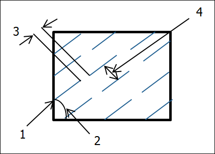
section component. The line patterns obtained are ProXsecXhatch structures that contain the following fields:
•  angle—Specifies the angle of the line patterns.
•  spacing—Specifies the distance between the line patterns.
•  offset—Specifies the offset of the first line in the pattern.
Note
The functions ProXsecCompXhatchGet(), ProXsecCompXhatchAdd(), and ProXsecCompXhatchReplace() support only the old hatching styles, that is, the *.xch file format.
The function ProXsecCompXhatchAdd() adds a line pattern to a specified cross section component. This function takes the handle to the cross section, the ID of the cross section component, the handle to the drawing view containing the cross section component and a pointer to the ProXsecXhatch object as its input arguments.
Note
If the cross section component already includes a line pattern, then the function ProXsecCompXhatchAdd() does not add a line pattern.
The function ProXsecCompXhatchReplace() replaces all existing line patterns of a specified cross section component with a new one.
The function ProXsecCompXhatchStyleGet() returns information about the style of hatch pattern in the specified cross section component. The output argument p_xhatch_style returns a ProXsecXhatchStyle handle. The structure ProXsecXhatchStyle contains the following information:
•  type—Specifies the type of hatch. The valid values are:
  PRO_XHATCH—Specifies that the cross section component is displayed as a hatch.
  PRO_XSEC_EXCLUDED—Specifies that the cross section is excluded for the specified assembly component.
  PRO_XSEC_FILL—Specifies that the cross section component is displayed as a solid.
  PRO_XHATCH_ERASED—Specifies that the cross section component is erased, that is, neither hatched nor filled.
•  ProXsecXhatchPattern—Specifies a structure that contains information about the hatch pattern in a cross section. It contains the following information:
  angle—Specifies the angle of the lines in the patterns.
  spacing—Specifies the distance between the lines in the patterns.
  offset—Specifies the offset of the first line in the pattern.
  font—Specifies a line style for the line pattern.
  color—Specifies the color for the line pattern.
Note
The functions ProXsecCompXhatchGet() and ProXsecCompXhatchStyleSet() support only the old hatching styles, that is, the *.xch file format.
The function ProXsecCompXhatchStyleSet() sets the hatch pattern for the specified cross section component using the ProXsecXhatchStyle structure.
The function ProXsecCompNewXhatchStyleGet() returns information about the style of old and new, that is, nonlinear hatch pattern in the specified cross section component. The output argument p_xhatch_style returns a ProXsecNewXhatchStyle handle. The structure ProXsecNewXhatchStyle contains the following information:
•  type—Specifies the type of hatch. The valid values are:
  PRO_XHATCH—Specifies that the cross section component is displayed as a hatch.
  PRO_XSEC_EXCLUDED—Specifies that the cross section is excluded for the specified assembly component.
  PRO_XSEC_FILL—Specifies that the cross section component is displayed as a solid.
  PRO_XHATCH_ERASED—Specifies that the cross section component is erased, that is, neither hatched nor filled.
•  ProXsecXhatchPattern—Specifies a structure that contains information about the old hatch pattern in a cross section. It contains the following information:
  angle—Specifies the angle of the lines in the patterns.
  spacing—Specifies the distance between the lines in the patterns.
  offset—Specifies the offset of the first line in the pattern.
  font—Specifies a line style for the line pattern.
  color—Specifies the color for the line pattern.
Note
When the cross section has old hatch patterns, the field *new_lines in the structure ProXsecNewXhatchStyle is returned as NULL.
•  ProXsecNewXhatchPattern—Specifies a structure that contains information about the new hatch pattern in a cross section. It contains the following information:
Image
  1 X-Origin, Y-Origin
  2 Angle
  3 Delta X
  4 Delta Y
  angle—Specifies the angle of the lines in the patterns.
  x_origin—Specifies the origin of the first pattern line along the x-axis.
  y_origin—Specifies the origin of the first pattern line along the y-axis.
  delta_x—This is used for dashed line pattern. Specifies the distance after which the next dashed line starts in a pattern.
  delta_y—This is used for both continuous and dashed line pattern. Specifies the distance between the pattern lines.
  dash—Specifies a dashed line pattern.
  num_dash—Specifies the number of dashes for the line pattern.
  color—Specifies the color for the line pattern.
Note
When the cross section has new hatch patterns, the field *old_lines in the structure ProXsecNewXhatchStyle is returned as NULL.
The function ProXsecCompNewXhatchStyleSet() sets the hatch pattern for the specified cross section component using the ProXsecNewXhatchStyle structure.
Note
When you set new hatch patterns for the cross section, pass the field *old_lines as NULL in the structure ProXsecNewXhatchStyle. Similarly, when you set old hatch patterns for a cross section, pass the field *new_lines as NULL in the structure ProXsecNewXhatchStyle.
Use the function ProXsecCompNewXhatchStyleSetByName() to replace an existing hatch pattern with the specified hatch pattern. This function supports only new, that is, nonlinear hatch patterns. For the replacing hatch pattern, you can also set the type and color attributes.